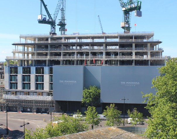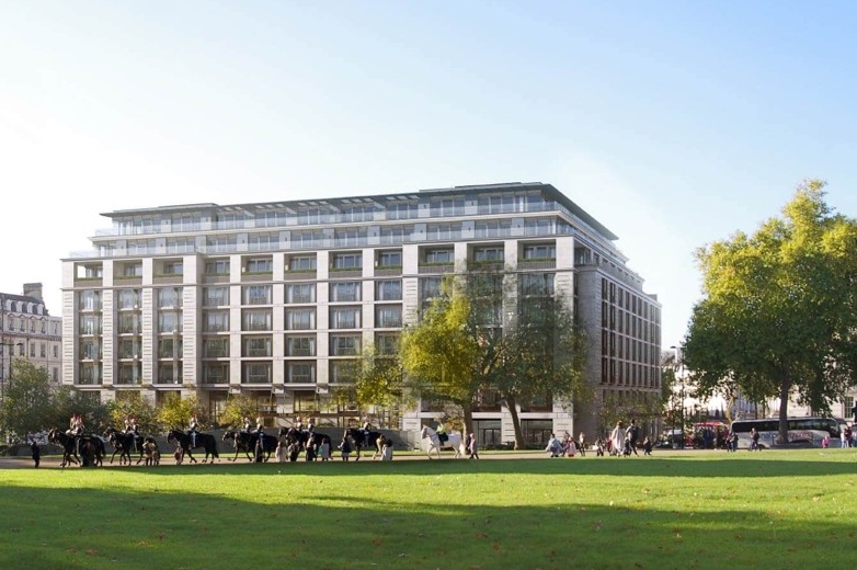
1-5 Grosvenor Place
Peninsula Development
The Peninsula Hotel development at 1-5 Grosvenor Place comprises an 8-storey high structure with additional 5 levels of deep basement built in a top-down-bottom-up fashion.
Our client’s scope included all the earthworks items associated with the top-down part of the basement build, extending to temporary support of the secant pile wall at various levels, usage, inspection and maintenance of the haulage ramp to support earth removal activities.
Swanton Consulting was supporting its client with all the necessary temporary works designs, namely:
– Design of a 27m long bridge and two no. loading gantries
– Bracing design for the plunge columns supporting the bridge
– Various propping designs for the capping beam and the secant pile wall
– Berm and batter designs, slope stability analyses
– Trench wall designs
– Structural strengthening and thrust-block design for supporting the swimming pool propping at B4 level
HAULAGE RAMP
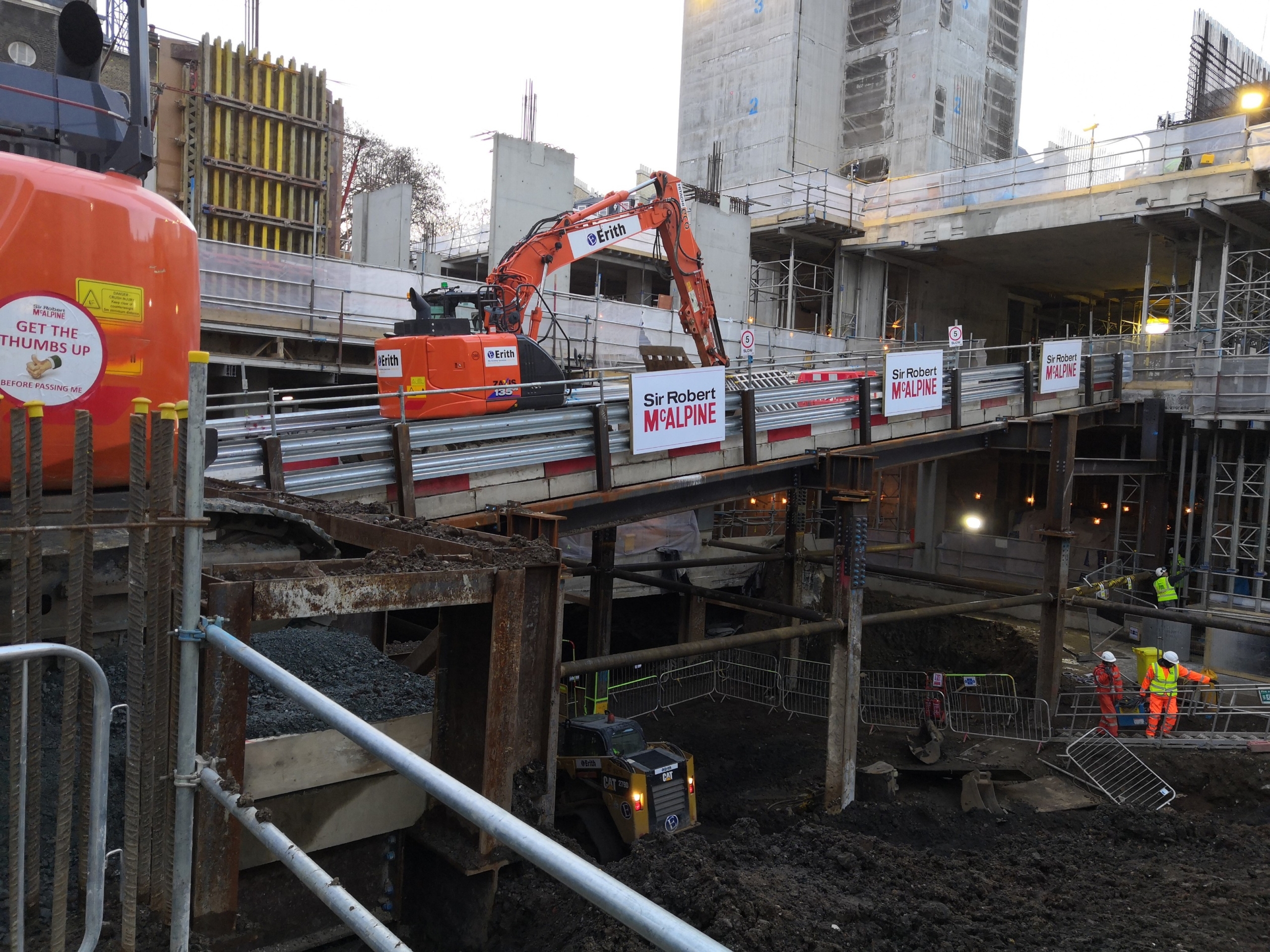
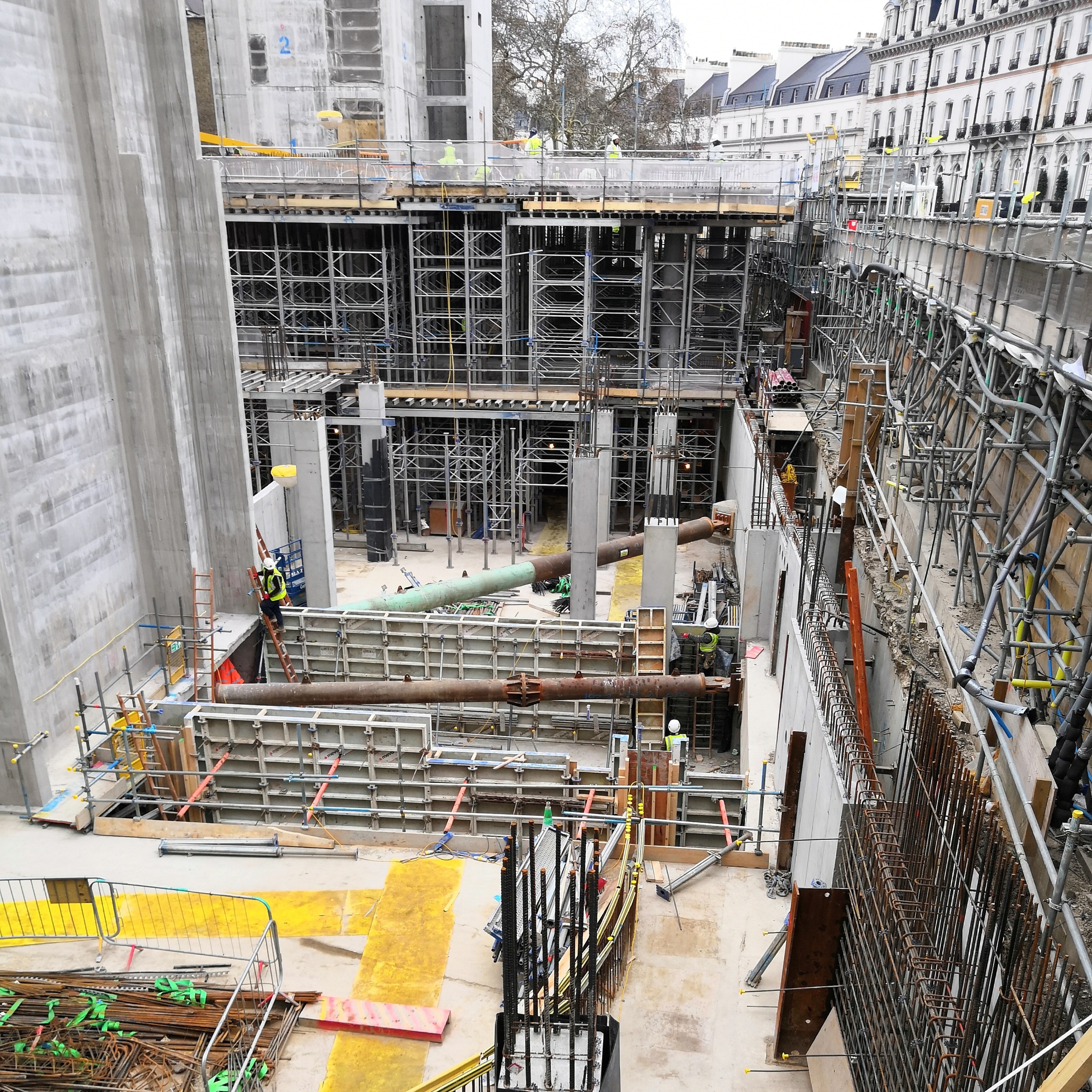
The haulage ramp was one of the key elements to the success of the project, as it was built right during the very beginning of the project and used throughout without any issues and downtime necessary for maintenance or reparations. The brief was to design and build a 27m span bridge across the mole hole, connecting the lower ground floor level on the Halkin Street side with the ground floor level on the Grosvenor Crescent side, a 3.37m difference in level and 26.8m horizontal span, with two loading gantries positioned on the sides, one at each level. The bridge had to be serviceable by two no. fully loaded 32t tipper lorries at any given time or alternatively a 44t articulated lorry. Additionally, the option of tracking a 60-tonne clamshell excavator needed to be included into the loading scenarios. The same excavator was used on either of the gantries, initially only on the Halkin street side, but at the time of the double-height dig of the B3 and B4 levels, both gantries had a clamshell excavator in operation. Peak usage frequency was planned to be 60 loads per day with one loading gantry and 100 loads per day with two gantries. The bridge and the gantries were supported on 10 no. plunge columns arranged on a 6.7m x 6.7m grid, except for the Grosvenor Crescent side where the permanent RC columns and beams were utilised as supports. To offer the necessary movement allowance against thermal loads, the support points were carefully coordinated by strategic placement of free and guided elastomeric bearings and horizontally slotted holes in the steel members. This way the necessary allowance for movement was achieved, but at the same time the acceleration/braking and accidental impact forces were all transferred back into the slabs of the permanent structure, utilising them as horizontal bracing elements in order to reduce the potential sway that could occur as the top-down dig progressed. This horizontal support system was completed by tie bar bracing between plunge columns and structural slabs on each subsequent level, built as the dig progressed towards the B5 level.
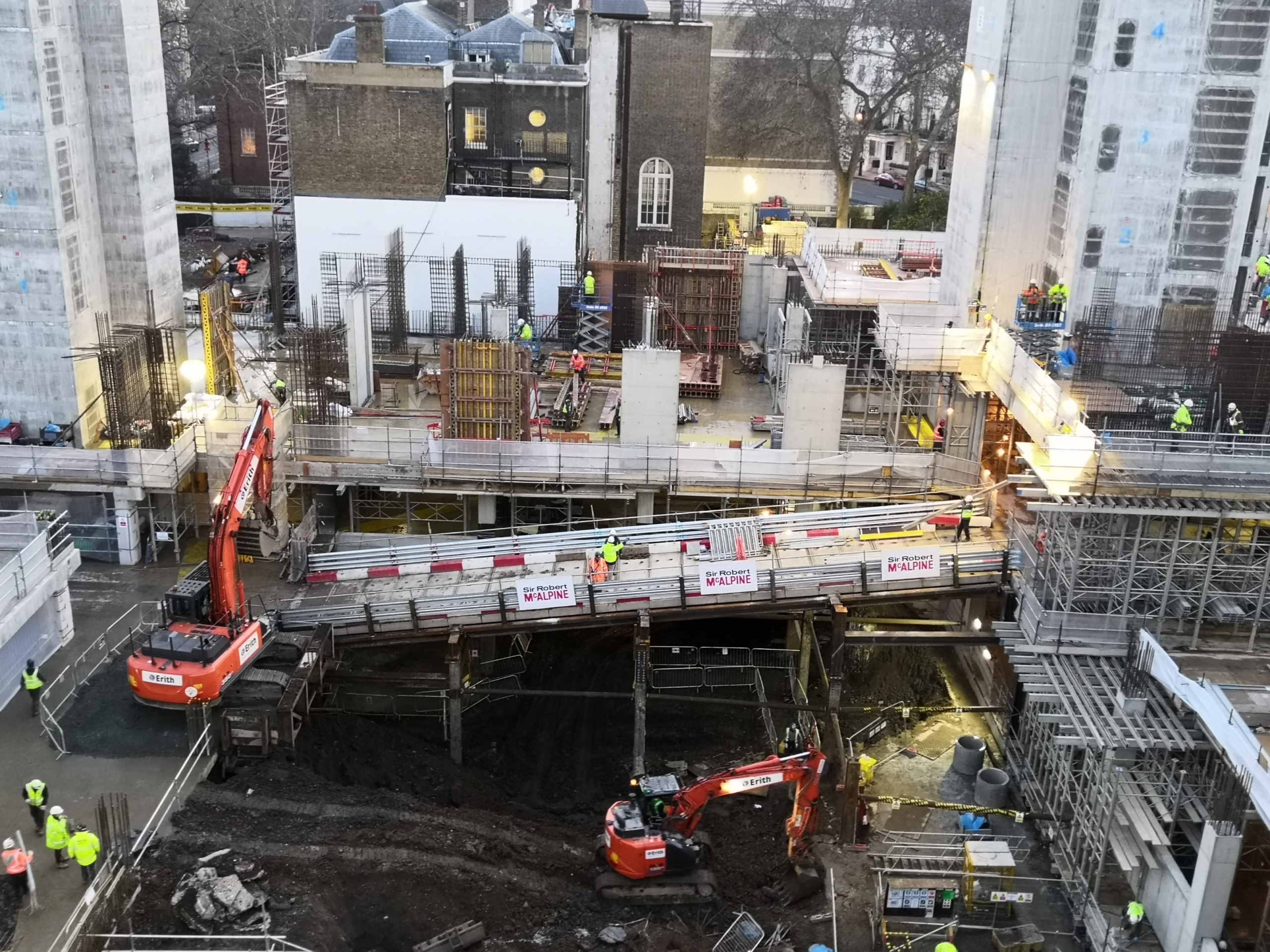
View of the haulage ramp from the welfare units
Excavator parked on bridge
PROPPING TO BASEMENT
Propping design for the capping beam and the B3 level propping involved heavy duty CHS props with axial loads including thermal effects reaching 5.5 MN in some cases. Prop P4 at capping beam level was a particularly challenging case at the removal stage, as its 14-tonne weight and 25m length required careful consideration of the health and safety implications and residual risks.
The structural strengthening solution designed for the Swimming Pool Propping at level B5 is a perfect example of Swanton Consulting’s capabilities to offer simple solutions for complex problems. The propping system for the base of the secant pile retaining wall was designed by others, while our scope was limited to design the strengthening of the swimming pool wall where the most loaded props are located.
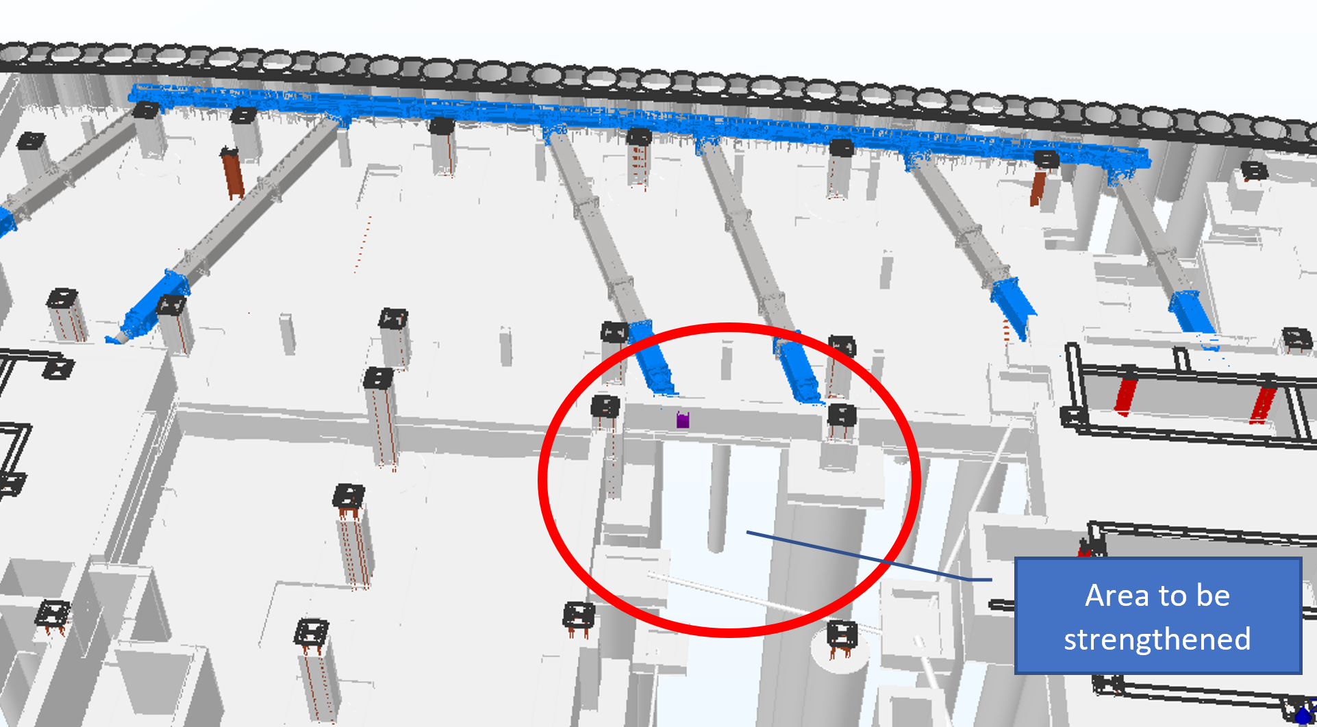
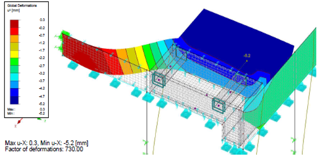
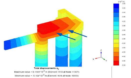
We proposed a load sharing solution where the prop reaction is shared by the permanent works members (walls, pile caps, piles) and ultimately taken down to the clay via the piles and the rest to be transferred to the clay at high level via a thrust block cast behind the wall immediately supporting the props. To achieve this load sharing we assessed ground movements and strains in a complex 3D Plaxis model, use the obtained deflections to calibrate the RFEM structural calculation model in order to check the structural elements and design the additional wall thickening and the necessary reinforcement.
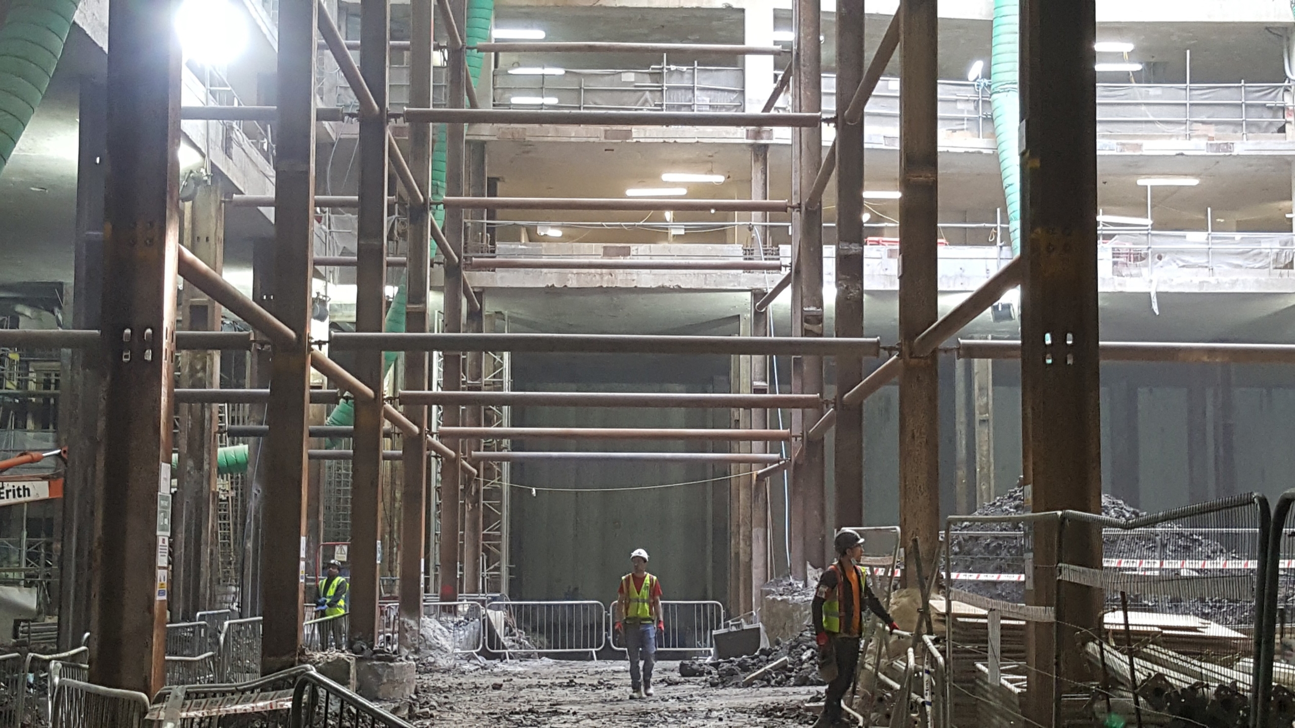
Haulage ramp structure views from the basement