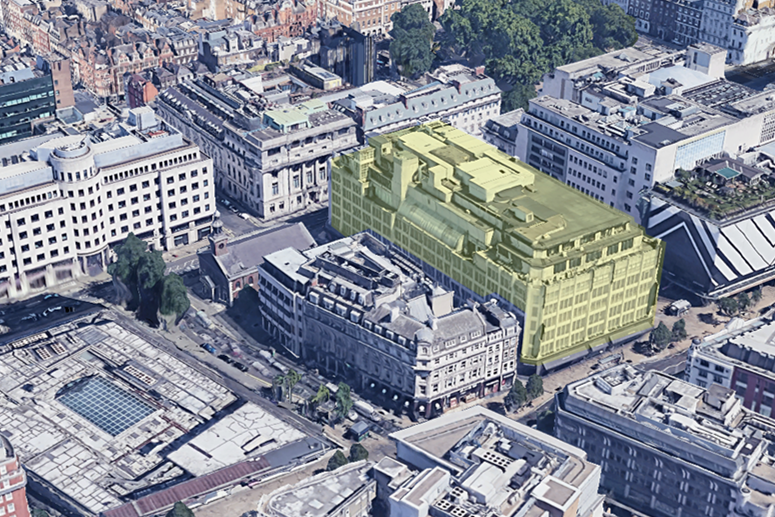
318 Oxford Street
This six-storey high building, erected in 1937, served as a bustling department store throughout its entire history of use. Structurally, it consists of a steel frame constructed from compound riveted steel sections, reflecting the construction practices of its time. However, an uncommon practice was employed for the internal columns, which are made of solid circular steel sections. Additionally, unlike many buildings of its era, the floors are constructed from prefabricated concrete I-beams rather than the more common hollow-pot floors. The building’s façade is of steel-framed construction, internally clad with brickwork and externally covered in stone.
Erith Contractors has tasked Swanton Consulting with providing the necessary temporary works designs for the complex cut and carve development of 318 Oxford Street project. The core scope of works included:
- complete demolition of the existing structure down to level 06 followed by the construction of three new upper floors.
- partial demolition and subsequent reconstruction of the level 06 floor.
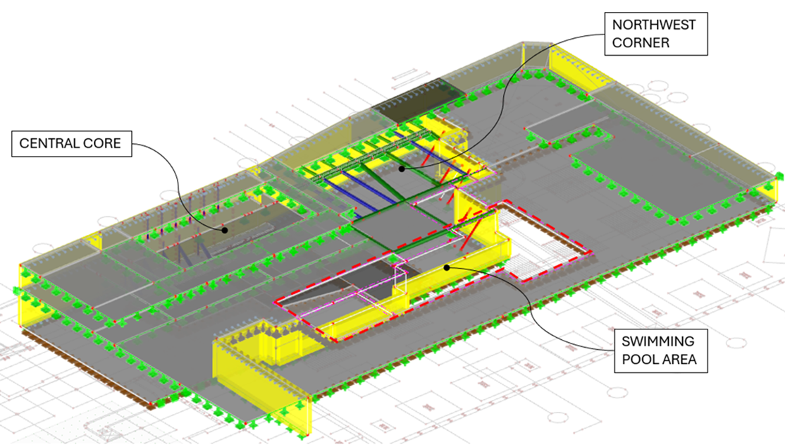
- demolition and reconstruction of all floors within the northwest corner area of the building.
- demolition of central areas along Chapel Place to facilitate the installation of a new core.
- extensive demolition of a significant portion of the 1st-floor slab to create a double-height space for the office entrance.
- enabling works to prepare for the installation of a proposed swimming pool at the basement level.
Main temporary works designs related to above list are outlined below.
Central core façade temporary propping scheme
Central and Northwest façade temporary propping
The west façade of the building needed to be restrained before demolishing portions of the structure in the central and northwest corner areas. We employed the RMD Slimshor system and designed flying shores restrained against the retained section of the building. Temporary props spanned between façade columns and internal columns, installed below existing floor levels to allow convenient access for demolition and later installation of the new slab. The positions of the props were coordinated with the new proposed structure. Existing internal columns were checked for eccentric loads transferred by the temporary props.
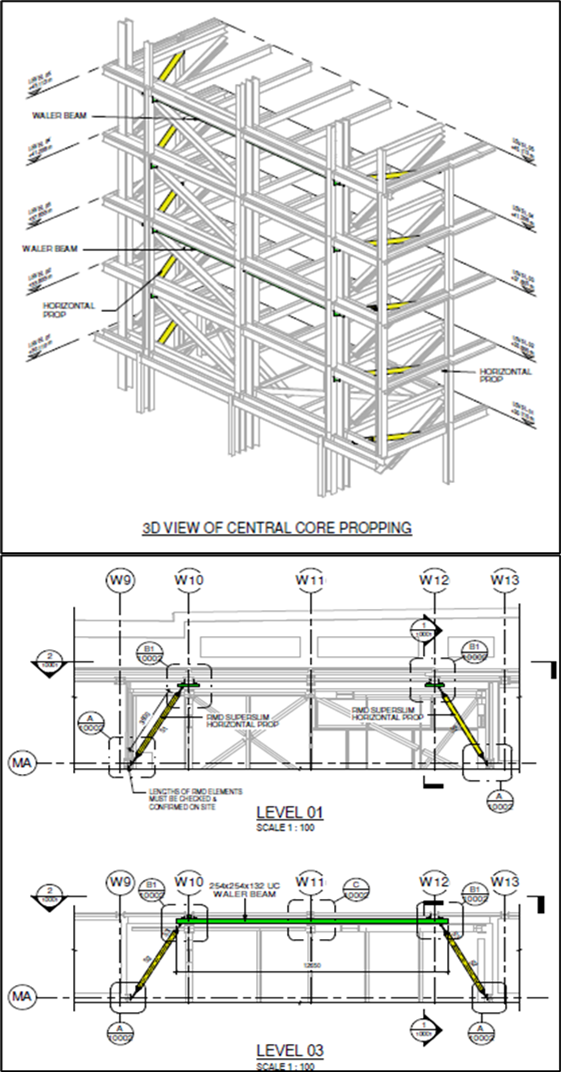
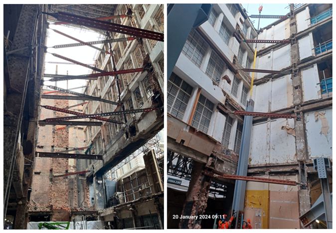
Northwest corner façade & Central core façade – propping scheme as built
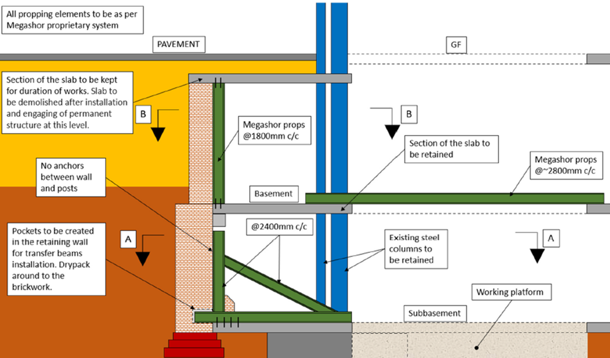
Basement propping
Temporary propping design was required for three sections of an existing masonry retaining wall along Chapel Place. The most challenging section was the central area, requiring temporary supports for the retaining wall due to the planned partial demolition of the ground floor, basement, and ground-bearing subbasement slabs. At each level, an 8-meter-wide void was requested to be created to allow for new steel core installation. A 3-meter-wide portion of the existing slab at every floor was excluded from the demolition scope. We proposed a propping arrangement, detailing the design approach for each level of the retaining wall as described below:
- at the subbasement level, we utilized raking props to support the wall against the retained 3-meter portion of the slab. Additionally, we planned for a piling mat to be installed in a hit-and-miss sequence to secure the scheme against sliding. By avoiding props over the piling platform, piling works in the considered area were significantly facilitated.
- at the basement level, our proposal involved replicating the existing support conditions by installing horizontal props between the retained sections of the B1 slab, spanning over the newly created 8-meter void. Locations of these props were coordinated with the installation of the new steel core.
- we decided to use retained 3-meter portion of the ground floor slab as a temporary support of the wall at this level. We considered remaining floor as a deep beam, and we utilized the Strut-and-Tie Model method (STM) to analyse and justify the scheme. It was considered that the existing concrete would work in compression, while tension would be transferred by the existing steel beams and steel filler joists.
We used RFEM 5 software to build a finite element model of the existing retaining wall, incorporating the retained portions of the basement floors.
Retaining wall at central area – proposed propping scheme
Existing retaining walls – RFEM5 calculation model
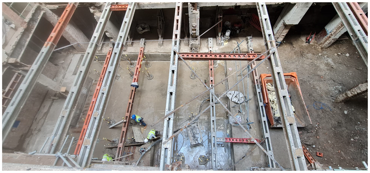
At the later stage, piling mat supporting bottom of the retaining wall was required to be excavated for the new B2 slab. We proposed and designed temporary horizontal Megashor props spanning over the excavation to maintain restraint to the wall at this level.
However, the most challenging aspect of this task was managing water ingress due to the high-water table being just below existing slab level. New B2 raft slab was proposed to be 1.2m thick. Water entering excavation was required to be stopped to enable installation of blinding, waterproofing, reinforcement and then to allow for concrete pouring. After reviewing the case we suggested to use permeation grouting around the entire perimeter of the excavation. Permeation grouting haven’t stopped water ingress completely however it stabilized the soil and prevented from washing out of the fine material. The remaining water that was still seeping into the excavation was gradually removed by the site drainage pumps.
Central core – basement propping ate levels B2 and B1
MF column jacking and foundation removal
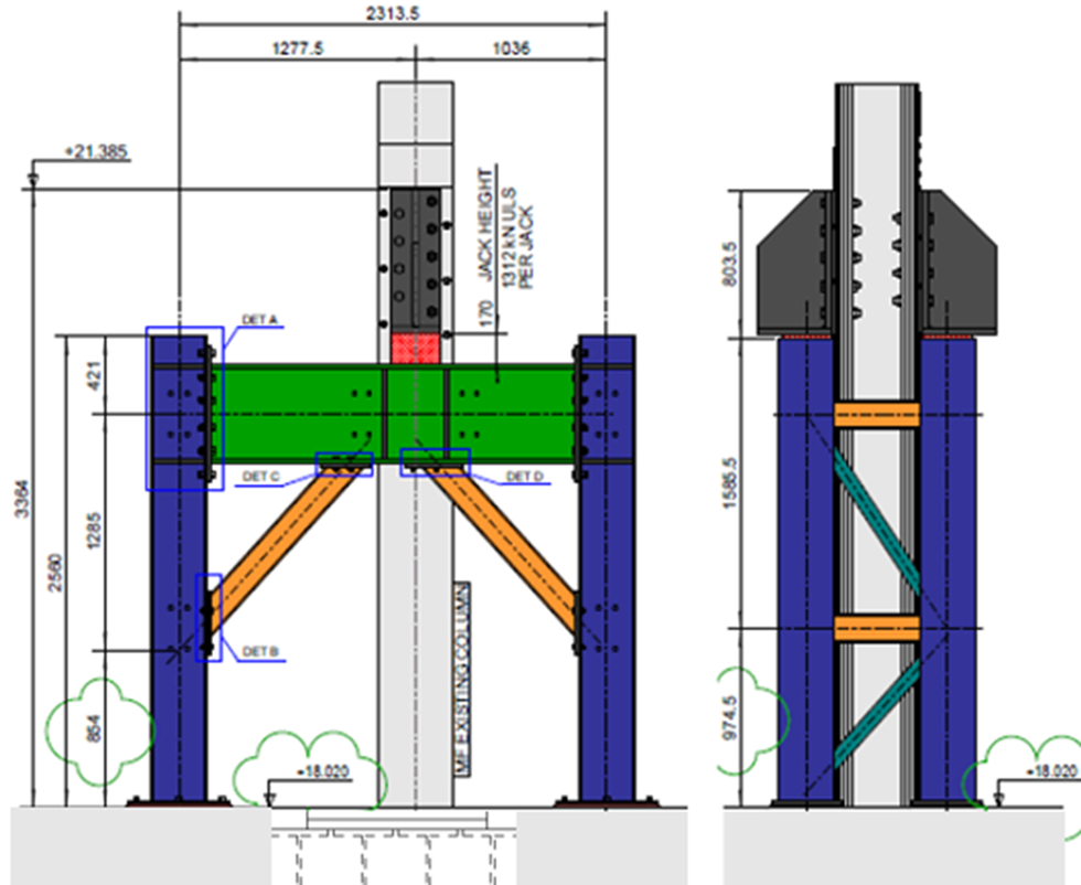
We have been tasked with designing a temporary support for an internal column at grid line MF to facilitate the partial removal of the existing foundation at B2 level, in order to construct a new lift pit according to the specifications provided by the permanent engineers.
The existing foundations consist of steel grillage construction, comprising two layers of steel beams embedded in a concrete footing. Permanent engineers’ proposal involved reinforcing the foundation using cored through piles and removing the top layer of the grillage, while retaining the bottom layer. This approach enabled to preserve most of the foundation’s area, thereby maximizing the utilization of the existing structure. We were able to justify retained portion of the existing foundation and utilize it as a support, significantly reducing the temporary works required for the MF column. We have opted for steel frames due to their lower overall cost compared to proprietary systems. Cheeseplates have been provided for connection with the existing column to accommodate existing rivets. The jacking operation was carried out by Swantest, a specialist division of Swanton Consulting, which provides structural testing, investigation, and remedial and strengthening solutions for complex projects.
Column MF proposed temporary propping scheme
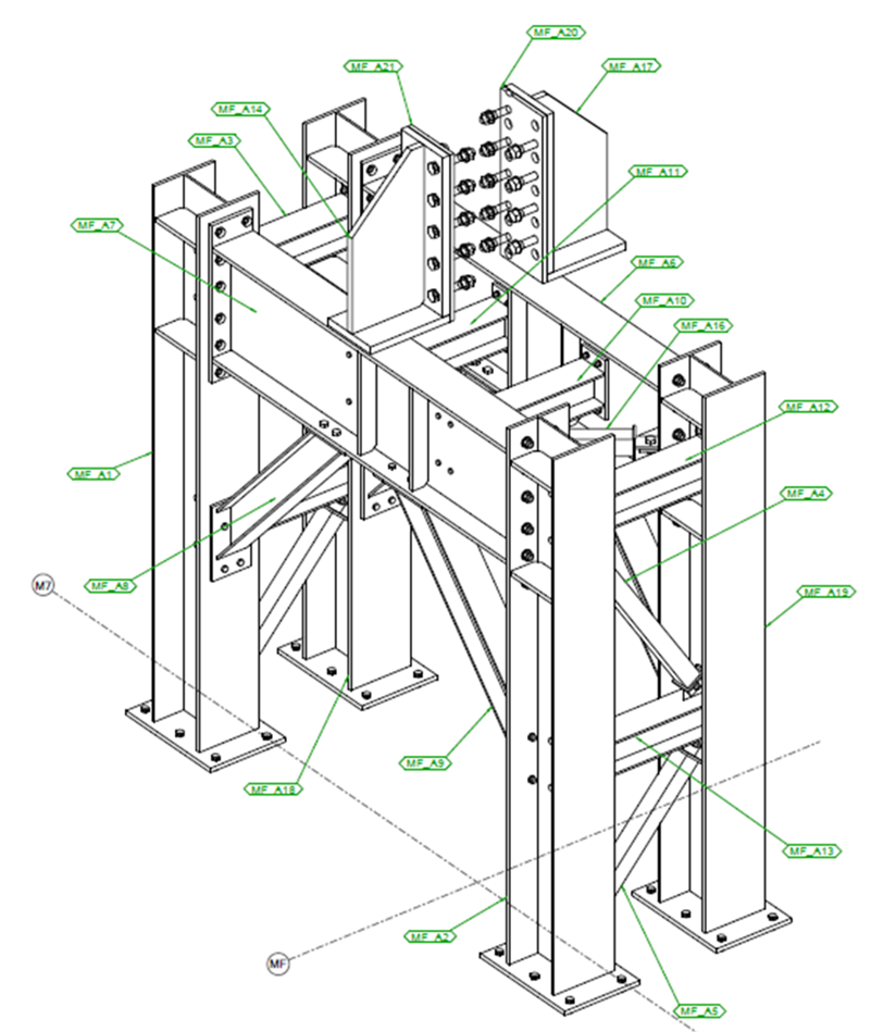
Column MF proposed temporary propping scheme – 3D
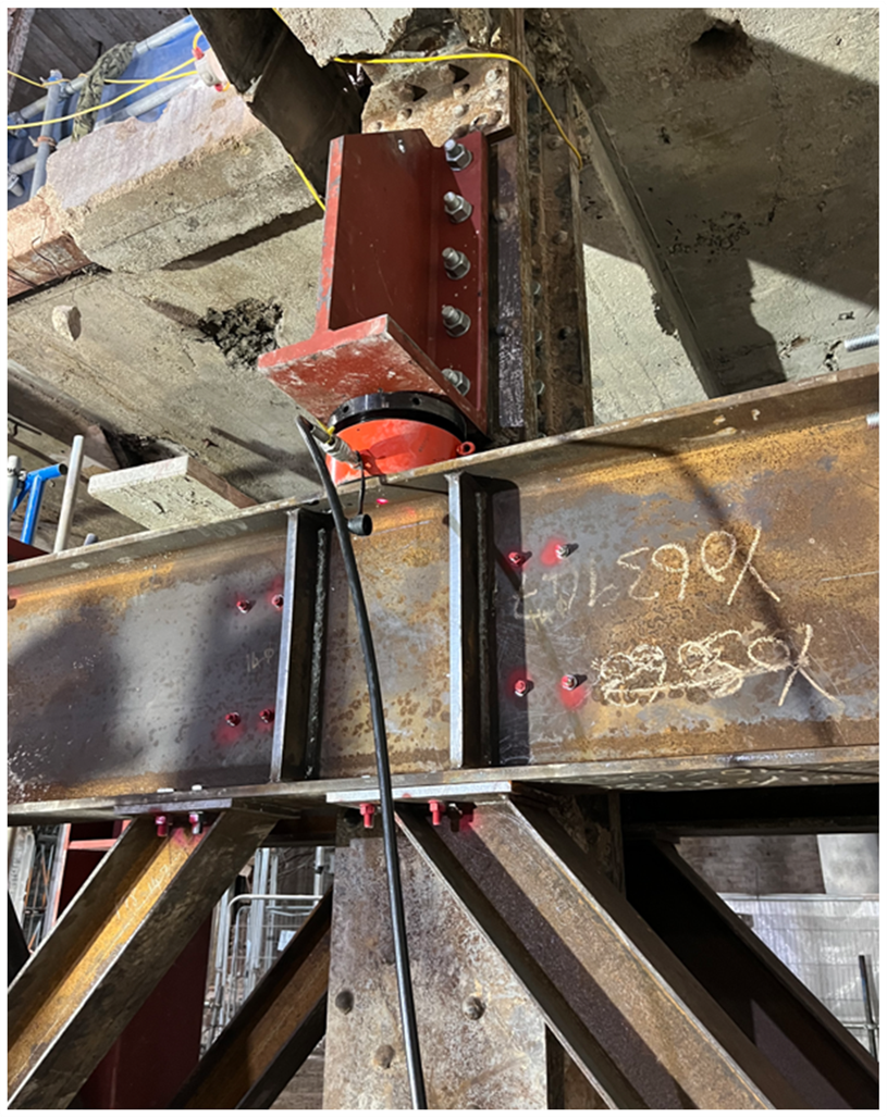
Column MF temporary frame as built
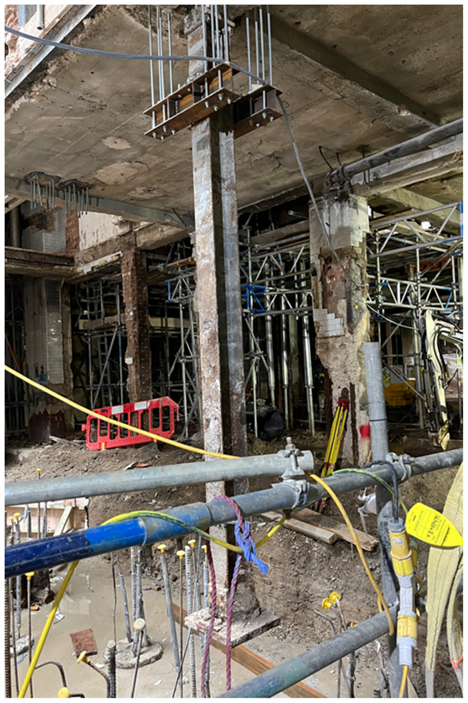
MD column temporary propping
A design for temporary propping of a single-storey high column, enabling the removal of the existing foundation, was requested by the client. Several constraints were present in the area, with the primary ones being the ongoing piling works followed by the installation of a new basement slab. To avoid props that would obstruct workspace for ground and concrete works, requiring careful sequencing and additional elements, we proposed an unconventional approach: a hanging temporary structure to support the column from the existing ground floor beams above.
We designed a set of steel beams, with two placed on top of the ground floor structure and the other two connected to the existing column. Threaded rod bars were used as tension elements in the scheme. This solution allowed us to avoid obstructing working space for the B2 level, where new piles and a new raft slab were required. Utilizing a reverse propping system made work in this area more sustainable and cost-effective
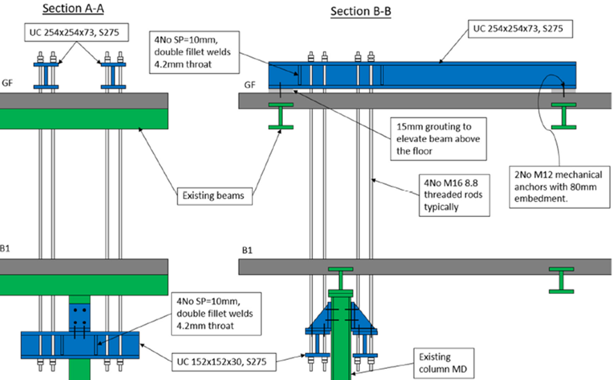
Column MD proposed temporary supporting scheme
Column MD temporary supporting scheme as built