One Sherwood Street
Piccadilly Lights
The One Sherwood Street project is a £250M development in the heart of London, behind the landmark attraction of the Piccadilly Lights.
Erith’s scope includes the demolition of almost all the structures in the block bounded by Sherwood Street, Glasshouse Street, Regent Street, Shaftesbury Avenue and Denman Street, except for the safeguarded areas currently occupied by Boots, Barclays, Gap and formerly Jamie’s Italian. The digital advertising board known as Piccadilly Lights is to be retained, kept functional and serviceable throughout the whole span of the demolition and rebuild works. Substructure works will start after demolition, in a top-down fashion, adding three levels of basement and building the Eastern and Western RC cores before handover to the main build contractor.
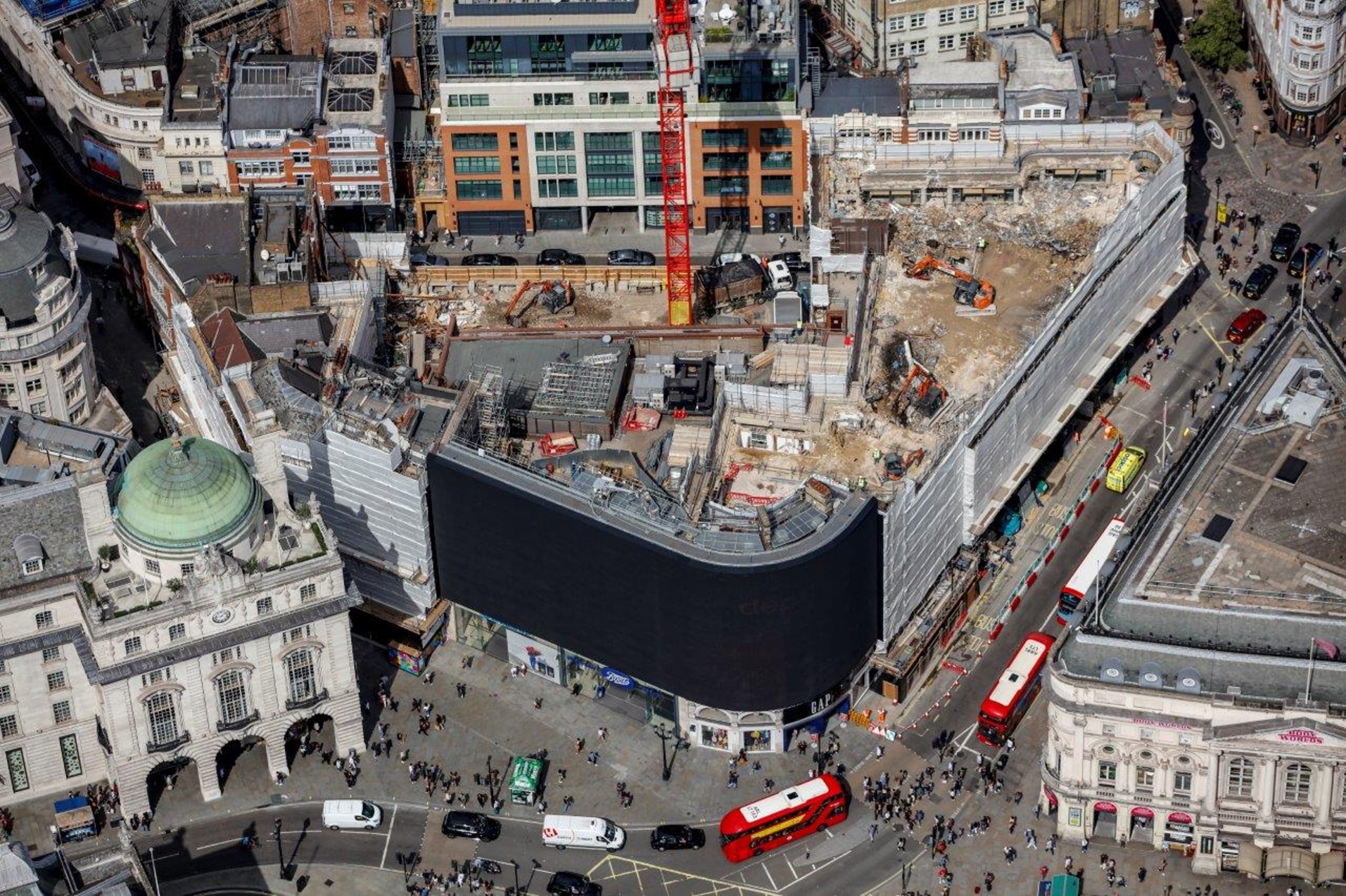
Aerial view of site
To support this complex enabling works package, Swanton Consulting was supporting its parent company with all the necessary temporary works designs, namely:
- Low-headroom piling and associated openings/temporary propping in the existing Shaftesbury/Denman Street basements
- Demolition back-propping
- Tower crane base
- Retention structure for the Piccadilly lights
- Sheet pile design for temporary and permanent stages
- Temporary propping of sheet piles
- Top-down basement design in the temporary stage
- Party wall support
- Welfare gantry grillage
- Structural assessment of the Jewel Bar involving complex coordination of temporary and permanent designs due to the retained listed ceiling at the first-floor level
- Structural assessments and temporary works design for crane outrigger loads
- Piling mats
- Point cloud survey and as-built model of the temporary structures and retained existing walls, staircases
BASEMENT ENABLING WORKS
One of the key project drivers for Erith was the possibility to remove the piling operations from the critical path by utilising low-headroom piling techniques with a small rig that can travel within the existing basement footprint.
The small size and the 3.5m headroom clearance needed for the piling operations were achievable in the basement of the Shaftesbury and Denman Street buildings, but enabling works were necessary to create the necessary travelling space by opening 3.5m by 4.m openings in some of the basement walls.
As only limited reinforcement information was available on one of the buildings and none whatsoever on the other, we have created a 3D model of the buildings based on a detailed geometry survey and assessed the capacity around the openings by computing the values of the principal stresses in the concrete. As the magnitude of the tensile stresses were lower than the tensile capacity of the concrete, no propping or strengthening was necessary.
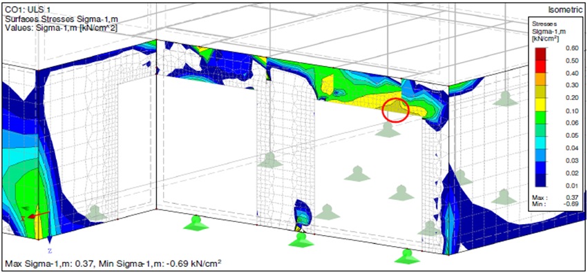
Principal tensile stresses in the basement wall
RETENTION OF PICADILLY LIGHTS
The retention structure of the Piccadilly Lights was separated in two distinct parts, the straight and the curved section. While the structural arrangement is different, both have to retain the recently installed galvanized supporting structure of the digital screens and the overhead maintenance unit in order to allow the panels to be serviceable. Additionally, both structures need to allow space for the erection of the follow-on permanent structure. This was particularly tricky in the case of the straight section because of the dense existing structure installed in the 70’s and modified later to allow for a plant room installation. To validate the accuracy of existing models and drawings we completed a 3D laser scan of original straight section members and overlaid it within our Tekla model, painstakingly checking all relevant members married up with the base model. The straight section existing steelwork provided little room to work around and the future steelwork took much of the remaining space, so the design started as a drafting exercise by modelling the structure into this space with the section sizes from the initial sizing to find the structural layout of the 3D model.
Calculation model of retention structures
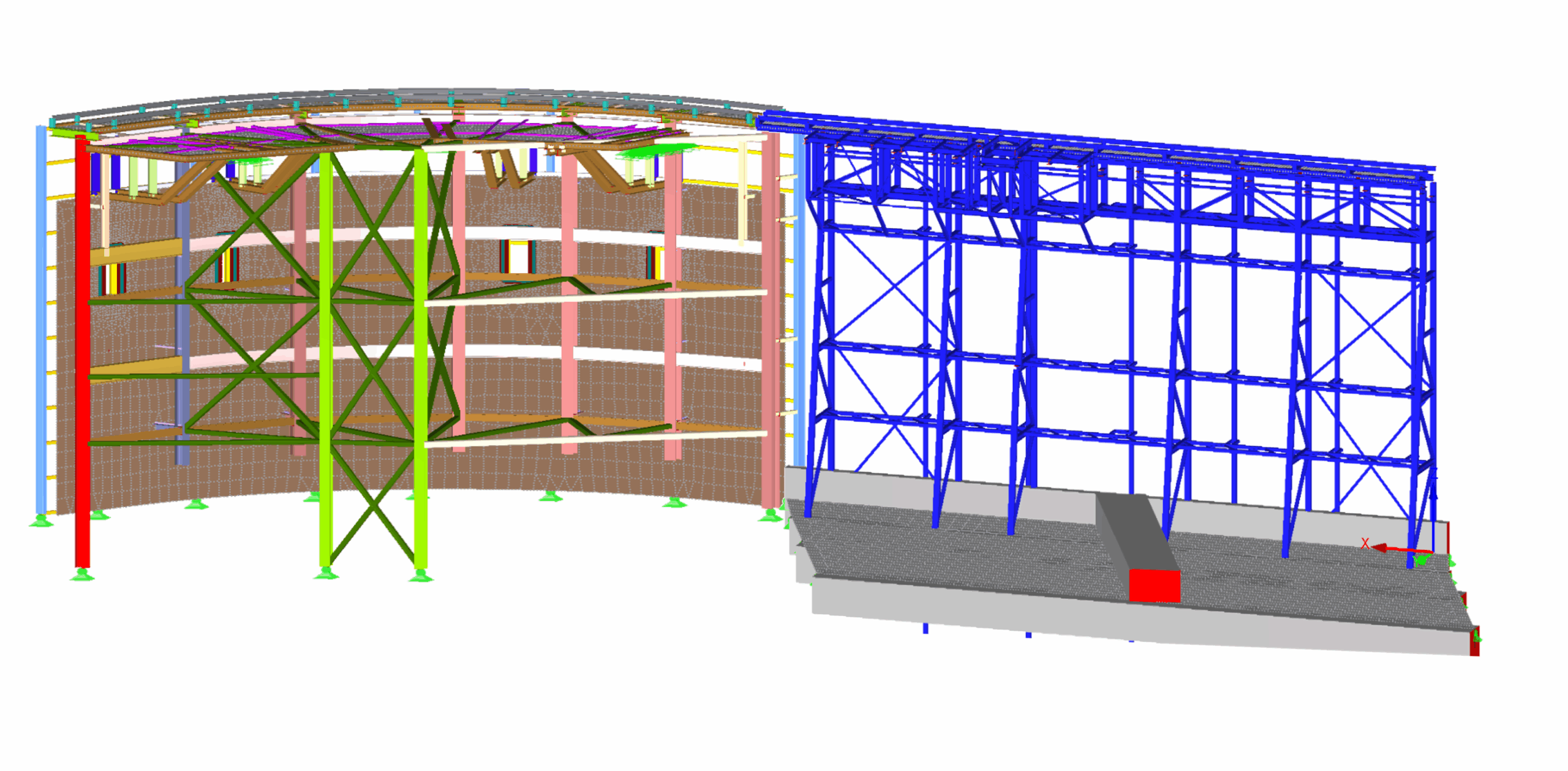
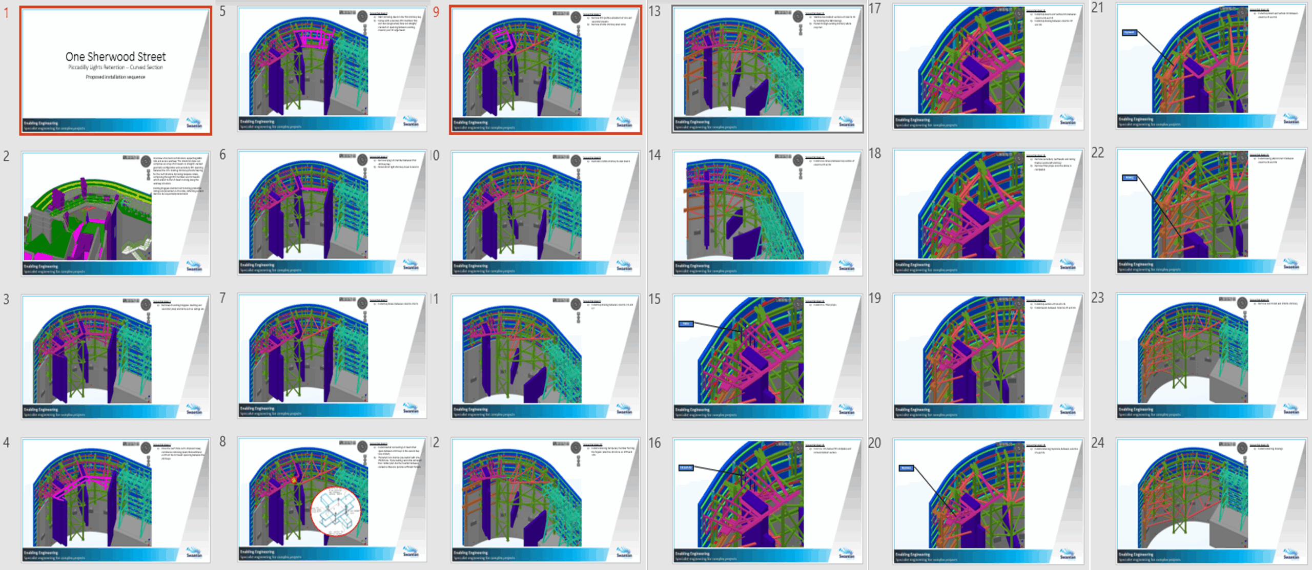
In the end the solution involved vertical A frame trusses, horizontal trusses, various cantilevers and bracing sequencing to install. In contrast the curved section was complicated by working in and around historical concrete and steel floors supported by masonry structure, while survey information of the existing steels was very limited due to them being covered by the masonry or being inaccessible to survey. Some permanent steelwork had to be incorporated into the solution to allow for a clearer space for the follow-on steel construction. Even with these measures some clashes remained insurmountable, so the erection of the steel structure was phased around the demolition with clear hols points of when and what needs to be installed in order to remove a certain part of the existing masonry/concrete.
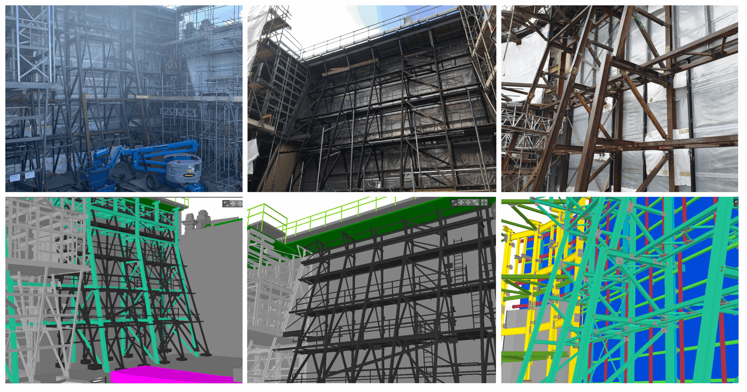
Straight Section: Phases in model and reality
Piccadilly Lights – Lego block instructions for Curve section sequencing: