Panther House
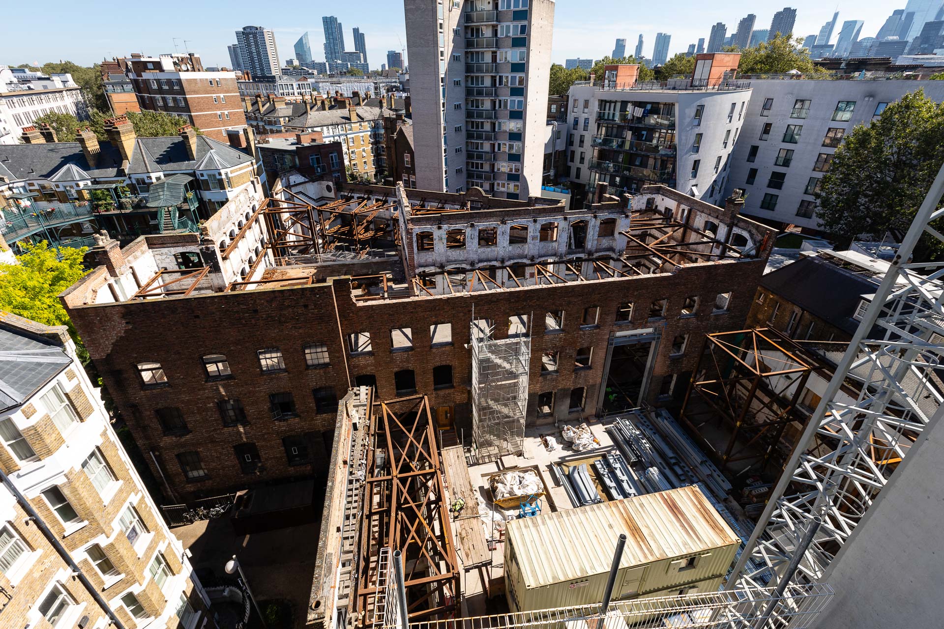
Erith Contractors appointed Swanton Consulting to design façade retention systems and further temporary works at the Panther House project which is located between Grays Inn Road and Mount Pleasant in Camden (London). The site was made up of three distinct parts, the Panther House, the Tram-Shed and Grays Inn Road.
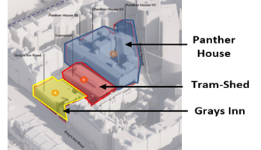
Keyplan of the Panther House, Grays Inn and Trams-Shed
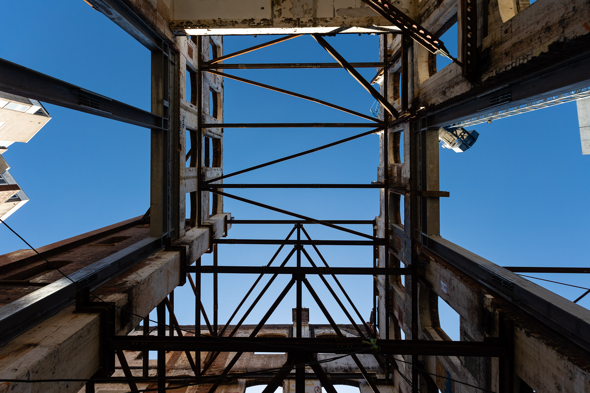
Below are presented some of the temporary works designed to allow the buildings’ demolition, the excavation works inside the site and the construction of the new development:
- The Northern and Southern façades of the Tram Shed was a bearing masonry wall braced laterally by concrete slabs and a metallic roof structure. Its retention scheme consisted of a series of towers with sufficient bracing and plunged columns.
- The retention scheme of the West Wing utilised the remaining of the opponent walls. By connecting the two sides of the wall with horizontal beams and braces, the lateral stability was achieved.
- The retention of the Northern wall consisted of two towers, internally and externally, founded on piles and with the walers placed inside the façade for easier access and installation. It was divided in two stages to allow the demolition and the new construction works. Stage 1 included installation of towers, walers and bracings to withstand the lateral loading and stage 2 the needling due to the demolition of the wall at lower level.
- Due to close proximity of the façade to Mount Pleasant road edge, the scheme for the East Wing scheme was assembled within the existing structure. The remaining structure was utilised as part of the retention system and cross sections were designed with double elements to provide access for the demolition works and the installation of the new ones.
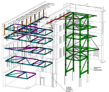
3D view of retention schemes at West Wing and Southern façade
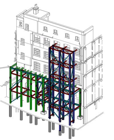
Temporary retention scheme at East Wing
Due to the space constraints within the Panther House building, for the formation of the masonry openings, permanents steel box frames were installed at an early stage. Additional double section temporary lintels were designed where the frames were single section so they could be installed in a sequence to support the masonry wall above.
The lateral restraint to the secant piled wall was provided through the early-on construction of the permanent slab to be used as logistic surface, supported on plunge CHS columns, braced in couples and founded on permanent/temporary piles.
The temporary works also included backpropping, slab assessments due to vehicles and scaffold loads, underpinning, two tower crane bases and sequence drawings for installation and removal of the scheme.
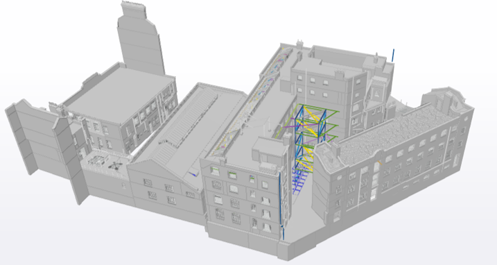
3D view of existing structure with retention schemes