Stonecutter
Erith Contractors appointed Swanton Consulting to provide a temporary works solution for the retention of the Hoop and Grapes pub due to the demolition of the existing neighbouring buildings. Due to the geometry of the building, the returning walls did not offer enough capacity to safely retain the masonry party walls subjected to wind and notional loads after the demolition of the adjacent structures.


Historical drawing of the Hoop & Grapes showing the foundations
The Hoop and Grapes was built in 1721 and undertook several modifications in the 1990s. It also became a Grade II listed building in the 1990s as was the last pub with history of Fleet weddings. It is a five storey plus one level of basement building with typical floor height of 3.5m. The structure has load bearing masonry walls and masonry strip foundations with concrete slabs spanning onto the party walls (pattress plates and wall ties on the front and rear elevations indicated traditional construction).
The temporary retention scheme was designed to allow the demolition and excavation works surrounding the pub and the construction of the new structure, which provides the permanent lateral support to the Hoop and Grapes. The temporary structure was designed as stand-alone without taking into consideration the stiffness of the Hoop and Grapes. That was decided given the visual condition of the masonry and not having available information regarding the bricks and mortar type and strength.
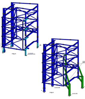
The solution consisted in a steelwork retention scheme strapping the building in a way that sufficient bracing was provided in the front and back face of the structure, while columns at the corners of the building transferred the forces down. Waler beams at slab levels were also provided to laterally support the party walls. The columns were supported in the existing capping beam and piles.


Temporary retention 3D view comparison between Phase 1 and Phase 2
The retention scheme was divided into two phases to allow the demolition and the new construction works. Phase 1 was installed while the existing building was still in place and the structure had to be supported at Ground Floor level. The change to Phase 2 progressed together with the demolition works and the supports changed from the Ground Floor to the top of the existing capping beam.
The design included the temporary retention scheme analysed with an FEA software, additional temporary works like backpropping to allow for the installation of it, checks on the masonry wall and sequence drawings for installation and removal of the scheme.


Temporary retention 3D view
Installed retention scheme

